Subject Code & Title :- CSE2NFX Network Engineering Fundamentals
Assessment Type :- Assignment 3
Part A: Design the proposed network topology
Scenario :-
Digital Graphics Design (DGD) is a medium-size graphic design company located in Melbourne. It offers a wide range of graphic design services to different companies/clients to popularise their brands and help them with their publicity by creating state of the art pieces such as flyers logo multi media presentations magazine titles visiting cards websites profiles and adding graphics to existing marketing material as per the client’s requirements.
CSE2NFX Network Engineering Fundamentals Assignment 3

The office consists of two levels. As a part of their expansion the managing director of DGD has recently hired two more levels within the same building.
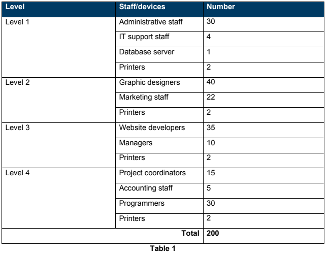
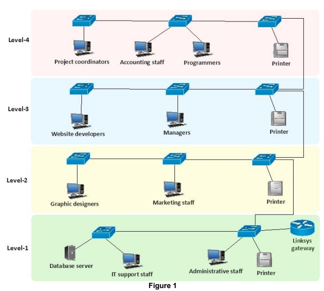
Table 1 shows the total number of staff and devices by location and Figure 1 illustrates the current network setup.
Note
• Figure 1 does not show all staff devices and printers.
All staff computers database server and printers are connected to D-Link DES-1026G 24-port 10/100 (Mbps) un managed switches via Cat3 cable. Also, a Linksys gateway device is connected to the network for internet access. All staff save their work related data over the local area network to a centralised database server (located on level 1).
How ever after the inception of two more levels, the network performance has dropped. Staff are complaining about the slow transfer of data to the database server also when sharing their work-related data over the local area network to other computers.
You have been appointed to redesign an appropriate local area network for DGD. The design should ideally be such that all the staff from one level can communicate with all other staff within the office with good speeds. The managing director of DGD also expects users to experience fast download speeds when browsing the internet. To avoid a slow and sluggish network the managing director of DGD has asked you to propose a LAN design to fulfil the above requirements.
Note
• This design needs only one router and the managing director has already purchased a Cisco router, model number 2811. So when attempting Task 1 (below), you are NOT required to suggest the router model.
• Your focus should be on improving the LAN performance.
CSE2NFX Network Engineering Fundamentals Assignment 3
Task 1: Produce a performance analysis document
Based on the above information you are required to produce a performance analysis document including the following.
a) Examine the existing local area network topology as shown in Figure 1 and perform an analysis on why the current network performance is slow.
b) Your recommendations for improving LAN performance.
Note
In your recommendations you need to focus on topology LAN devices, cables, etc.
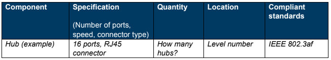
c) Recommended network components as part of improving the LAN performance. Provide a list of network components network component specifications quantity location and compliance IEEE standards of the selected networking components.
You can use Table 2 shown below as a template to list the components of your topology. The first two rows are examples. Starting from the third row you will have to provide an answer for the Cisco 2811 router and your chosen network components.
Note
Add all the written answers in a Word file named xxx_cse2nfx_assessment3.docx where xxx is your student number). Mention the task number in the Word file.
Part B: Implement IP routing in a simulated environment
Scenario :-
Digital Marketing (DM) is an enterprise marketing firm. As a part of their expansion DM is planning to open two new branches in Sydney and Canberra. The managing director of DM has decided to use IPv4 class B network address 172.16.0.0/16 for both new offices.
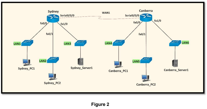
Before moving to the actual design and implementation phase, the managing director provided you with a simulated design of the proposed network as shown in Figure 2 which will assist you in under standing the entire network topology.
Note
• Figure 2 does not show all end devices and LAN switches.
• You need to use Cisco Packet Tracer software to configure the routers. Therefore for simulation purposes consider that all the routers are Cisco 2811 series.
• Only the devices shown in Figure 2 are to be used throughout this assessment.
• Add all the screenshots and written answers in a Word file named xxx_cse2nfx_assessment3.docx (where xxx is your student number). Mention the task number in the Word file.
Table 3 shows the number of host addresses (including WAN link) for both branches’ LAN.
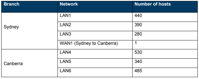

You have been hired as a network engineer to effectively design the IP addressing scheme for each LAN and WAN link by minimum address wastage. Each LAN has a different number of host requirements so in this scenario the FLSM method is not a good idea. You need to apply the VLSM method and perform the following task.
CSE2NFX Network Engineering Fundamentals Assignment 3
Task 1: Design the IP addressing scheme
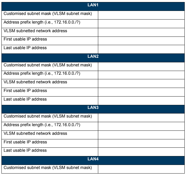
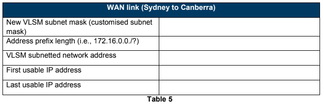
This is a critical planning step. To support your planning, two table templates (Table 4 and Table 5)are given below.
a) Fill Table 4 with the planned IP addressing scheme in dotted decimal notation for each LAN by using the VLSM method.
b) Fill Table 5 with the planned IP addressing scheme in dotted decimal notation for the WAN link by using the VLSM method.
Task 2: Build the topology
After designing the IP addressing scheme you need to create the network diagram shown in Figure 2 using a Cisco Packet Tracer. Use suitable cable types when cabling the devices for example Ethernet or serial. Label the devices as depicted in Figure 2.
a) Save the Cisco Packet Tracer file as xxx_cse2nfx_assessment3.pkt (where xxx is your student number).
b) Include a screenshot of your topology as evidence of the completion of this task.
CSE2NFX Network Engineering Fundamentals Assignment 3
Note
No configuration is required in Task 2 only a network diagram with relevant devices and cables.
Task 3: IP address assignment
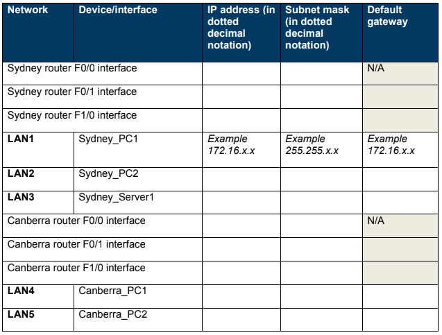
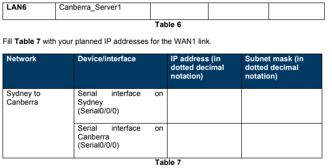
Fill Table 6 with the appropriate IP addresses, subnet masks and gateways, as per the IP addressing scheme from Task 1. Once you complete Tables 6 and 7 it will be easy for you to configure the Ethernet and serial interfaces in Task 4.
Task 4: Configure the Ethernet and serial interfaces
a) Configure Ethernet interfaces of all the end devices (i.e., Sydney_PC1, Sydney_PC2 Sydney_Server1, Canberra_PC1, Canberra_PC2 and Canberra_Server1) with the IP addresses, subnet masks and default gateways from Table 6.
b) For Sydney_PC1, Sydney_Server1, Canberra_PC1 and Canberra_Server1 take screenshots of the completed IP configuration window as evidence of the completion of this task and include them in the Word file.
c) Configure and activate the Ethernet and serial interfaces on each router using IP addresses and subnet masks from Tables 6 and 7.
CSE2NFX Network Engineering Fundamentals Assignment 3
Note
Configure the serial interface clock rate as 128,000.
d) Issue the command ‘show ip interface brief’ on both routers and provide screenshots of the output.
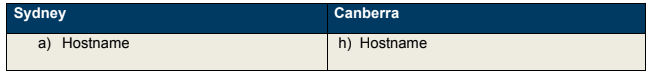
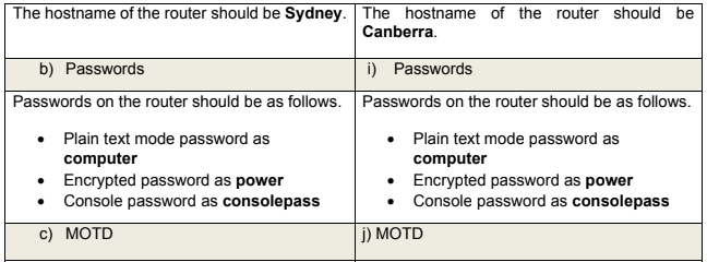
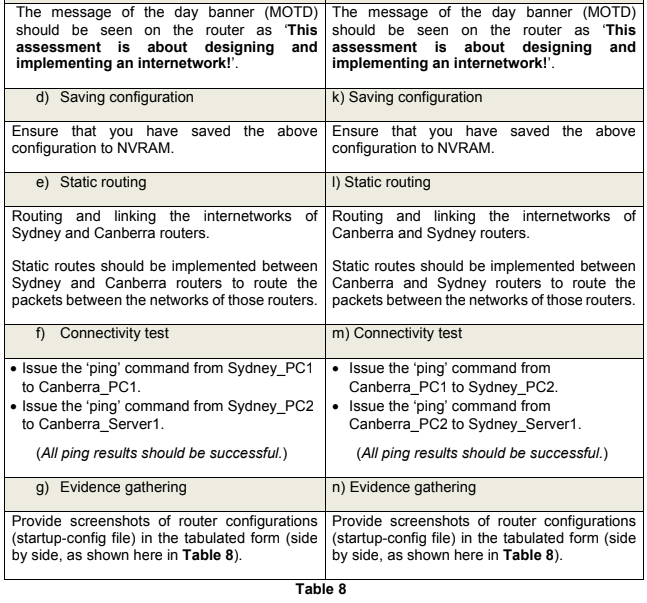
Task 5: Configure the Sydney and Canberra routers
Perform basic configuration of both routers (i.e., Sydney and Canberra) as per the given instructions in Table 8 (below).
Part C: Short answer questions
Note
Part C of this assessment is not YES/NO answers. Each of the questions should be answered in an elaborated form with pros and cons to support your answer.
CSE2NFX Network Engineering Fundamentals Assignment 3
Q1. In Part B, Task 1, you have designed the IP addressing scheme for each of the six LANs by using the VLSM method. If the number of users is doubled in each LAN, will the current LAN be able to accommodate the additional users? Explain in detail to support your answer.
Q2. In Part B, Task 4, you have configured Ethernet and serial interfaces. Imagine, you have configured Ethernet and serial interfaces for the Sydney router, but you have ONLY configured an Ethernet interface on the Canberra router. In this situation what will happen? Explain in detail to support your answer.
Q3. Provide a scenario where the FLSM method is better than the VLSM method and the VLSM method is better than the FLSM? Explain in detail.
ORDER This CSE2NFX Network Engineering Fundamentals Assignment NOW And Get Instant Discount